Ternary Digital Clock with Arduino

1. Introduction
Probably you have seen many binary clocks, but it is not so usual a ternary digital clock.
This project introduce an original ternary digital clock running with Arduino, very simple to be assembled and unlike anything you've ever seen!
Ternary clocks represent the hour and minute in Ternary Numeral System what means the numbers are powers of 3 (or base 3).
As comparison, binary numbers the base is 2 and in decimal system, the base is 10.
Maybe it sounds a little complicated, but the reading and use of ternary clock is very simple.Let's see the project and I hope you enjoy it!
2. Numeral Systems
Numbers are everywhere in our lives and the decimal numeral system is what we use everyday.
In fact there are many different numeral base such as binary, octal or hexa. Specially for computing, binary is the primary reference.
It is easy to transform any number in different base with a minimum of simple calculations.
Note: If you want more information, I suggest you read the article Numbers in Different Bases of Oxford College.
The ternary numeral consists basically in numbers written with 0, 1 or 2.
For example:
Decimal: 15 = 1 * 10 + 5 * 1
Ternary: 0120 = 0 * 27 + 1 * 9 + 2 * 3 + 0 * 1
The following table shows the conversion from decimal (0 to 9) to ternary.

The strategy of the program applies two different colors representing the digits 1 and 2 of ternary numbers.
0:No color
1: Green
2: Red
These colors are used on RGB LEDs to see the hours and minutes as shown on pictures below.

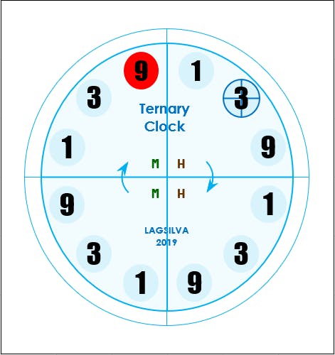
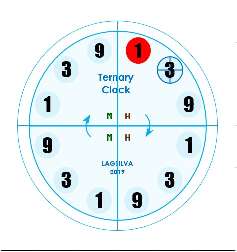
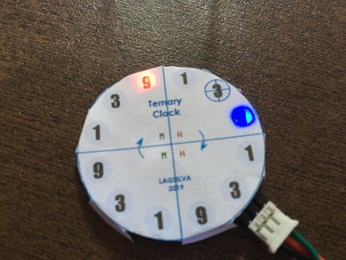
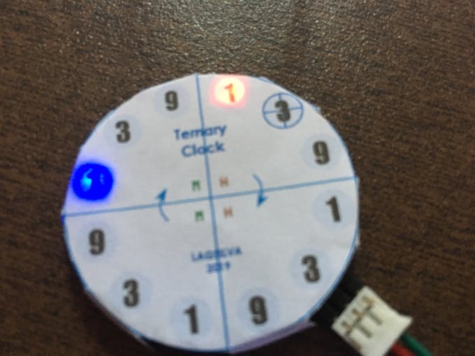
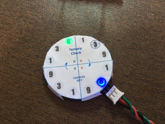
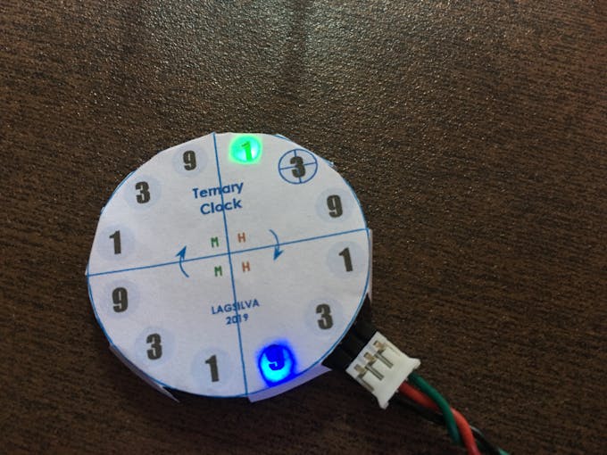
3. Clock Setup
For the setup of hour and minute there are two push buttons to be used:
-Left push button: operation mode setting
- Mode 0: regular clock operation
- Mode 1: Tens of hour (upper left LED in red)
- Mode 2: Units of hour (upper right LED in red)
- Mode 3: Tens of minute (upper left LED in green)
- Mode 4: Units of minute (upper right LED in green)
- Right push button: time setting (hour/minute)
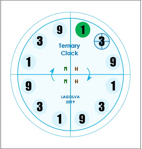
According to the selected mode, the LED displays numbers from 0 to 9 in blue.
Press the button until the correct number is displayed, and then press the Mode button to move to the next setting.
Note: The reference "zero" is printed as "3" marked crosswise.
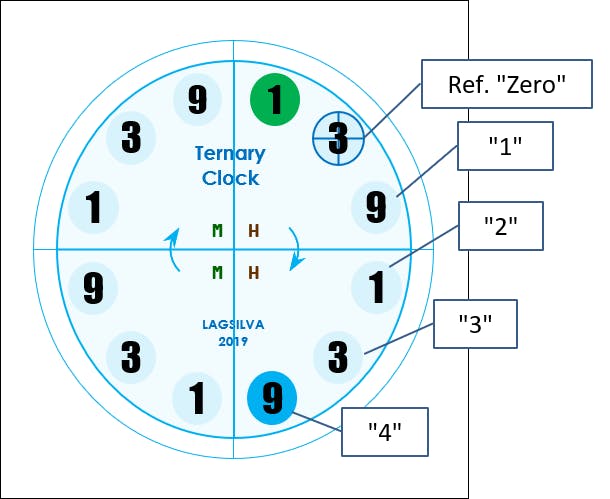
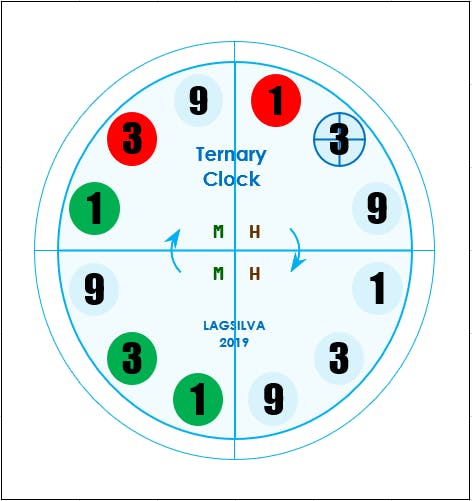
4. Clock Reading
The design proposal using 12 LED NeoPixels arranged in a circle remind us a traditional clock.
The clock is divided into four quadrants with 3 LEDs each.
The reading begins in the first quadrant by following clockwise based on LED color (green or red) and the its corresponding number (1, 3 or 9).
- Quadrants:
- 1st: Tens of hour
- 2nd: Units of hour
- 3rd: Tens of minute
- 4th: Units of minute
- LED colors:
- Green: the number is the printed.
- Red: the number is twice the printed.
-Example:
In the following example, the time is:
- Hour (1st digit) = 1 x 2 (red) = 2
- Hour (2nd digit) = 0
- Minute (1st digit) = 1 x 1 (green) + 3 x 1 (green) = 1 + 3 = 4
- Minute (2nd digit) = 1 x 1 (green) + 3 x 2 (red) = 1 + 6 = 7
So, the time is: 20:47 hs
/*
  Project:  Ternary Digital Clock with RTC
  Hardware: Arduino UNO-R3 / Strip LED
  Author:   LAGSILVA
  Revision: 1.3
  Date:     26.Jan.2019
  License:  CC BY-NC-ND 4.0
            (Attribution-NonCommercial-NoDerivatives 4.0 International)
*/

#include <Time.h>                  // Time library
#include <TimeLib.h>
#include <Wire.h>                  // Library for DS1307RTC - Pins of Arduino UNO: A4 (SDA), A5 (SCL)
#include <DS1307RTC.h>             // Library for Real Time Clock
#define DS1307_I2C_ADDRESS 0x68    // This is the I2C address (RTC)
#include <Adafruit_NeoPixel.h>

#define ledPin 7

// Parameter 1 = number of pixels in strip
// Parameter 2 = pin number (most are valid)
// Parameter 3 = pixel type flags, add together as needed:
//   NEO_KHZ800  800 KHz bitstream (most NeoPixel products w/WS2812 LEDs)
//   NEO_KHZ400  400 KHz (classic 'v1' (not v2) FLORA pixels, WS2811 drivers)
//   NEO_GRB     Pixels are wired for GRB bitstream (most NeoPixel products)
//   NEO_RGB     Pixels are wired for RGB bitstream (v1 FLORA pixels, not v2)

Adafruit_NeoPixel strip = Adafruit_NeoPixel(12, ledPin, NEO_GRB + NEO_KHZ800);

byte pos, cor[3];
byte dezH = 0, uniH = 0, dezM = 0, uniM = 0;
byte hora = 0, minuto = 0;


void setup() {

  pinMode(ledPin, OUTPUT);

  setSyncProvider(RTC.get); // Reading RTC (Real Time Clock)
  setSyncInterval(60);      // Set the number of seconds between re-sync

  //setTime(16, 11, 00, 26, 01, 2019);   // Setting Time and Date
  //RTC.set(now());                      // Setting RTC Time


  strip.setBrightness(10);  // Setting brightness of LED ring

  strip.begin();            // Initialize all pixels to 'off'

  for (byte k = 0; k < 12; k++) {
    strip.setPixelColor((k + 10) % 12, 128, 128, 0);
    strip.show();
    delay(500);
  }

  delay(2000);

  strip.clear();
  strip.show();

}


void loop() {

  strip.clear();

  hora = hour();
  minuto = minute();

  dezH = hora / 10;
  uniH = hora % 10;
  dezM = minuto / 10;
  uniM = minuto % 10;


  // Print Tens of Hour

  cor[0] = (dezH / 1 ) % 3;
  cor[1] = (dezH / 3 ) % 3;
  cor[2] = (dezH / 9 ) % 3;

  for (pos = 0; pos <= 2; pos++) {

    if (cor[pos] == 1) { // Green color
      strip.setPixelColor(pos + 9, 0, 255, 0);
    }

    if (cor[pos] == 2) { // Red Color
      strip.setPixelColor(pos + 9, 255, 0, 0);
    }

  }


  // Print Units of Hour

  cor[0] = (uniH / 1 ) % 3;
  cor[1] = (uniH / 3 ) % 3;
  cor[2] = (uniH / 9 ) % 3;

  for (pos = 0; pos <= 2; pos++) {

    if (cor[pos] == 1) { // Green color
      strip.setPixelColor(pos, 0, 255, 0);
    }

    if (cor[pos] == 2) { // Red Color
      strip.setPixelColor(pos, 255, 0, 0);
    }

  }


  // Print Tens of Minute

  cor[0] = (dezM / 1 ) % 3;
  cor[1] = (dezM / 3 ) % 3;
  cor[2] = (dezM / 9 ) % 3;

  for (pos = 0; pos <= 2; pos++) {

    if (cor[pos] == 1) { // Green color
      strip.setPixelColor(pos + 3, 0, 255, 0);
    }

    if (cor[pos] == 2) { // Red Color
      strip.setPixelColor(pos + 3, 255, 0, 0);
    }

  }


  // Print Units of Minute

  cor[0] = (uniM / 1 ) % 3;
  cor[1] = (uniM / 3 ) % 3;
  cor[2] = (uniM / 9 ) % 3;

  for (pos = 0; pos <= 2; pos++) {

    if (cor[pos] == 1) { // Green color
      strip.setPixelColor(pos + 6, 0, 255, 0);
    }

    if (cor[pos] == 2) { // Red Color
      strip.setPixelColor(pos + 6, 255, 0, 0);
    }

  }

  strip.show();

}
